

Date:2016-03-21 Categories:Industry News Hits:645
Due to the different composition of optocouplers, different detection methods should be adopted according to different structural characteristics. For example, when detecting the input end of ordinary optocoupler, the detection method of infrared light-emitting diode is generally referred to. For optocoupler with photosensitive triode output type, the detection method of photosensitive triode should be referred to when detecting the output end.
1. Multimeter detection method.
In this paper, mf50 pointer multimeter and 4-pin PC817 optocoupler are taken as examples to illustrate the specific detection method: firstly, according to Fig. 1 (a), the pointer multimeter is placed in the "R × 100" (or "R × 1K") resistance block, and the red and black lead are respectively connected to the two pins of the LED at the input end of the optocoupler. If there is a time when the index of the lead is infinite, but the resistance value of thousands to tens of thousands of Ohm after the exchange of red and black leads, then the pin connected with the black lead is the positive pole of the LED, and the pin connected with the red lead is the negative pole of the LED.
Then, as shown in Fig. 1 (b), connect the positive voltage at the input end of the optocoupler, put the pointer Multimeter in the "R × 100" resistance block, and connect the red and black lead to the two pins of the output end of the optocoupler respectively. If there is a time when the pin index is infinite (or the resistance value is large), but the red and black lead have a very small resistance value (< 100 Ω), then the pin connected to the black lead is the collector C of the internal NPN type photosensitive triode, and the pin connected to the red lead is the emitter E. When the forward voltage of the input terminal is cut off, the photosensitive triode should be cut off and the index of the multimeter should be infinite. In this way, not only the pin arrangement of 4-pin optocoupler PC817 is determined, but also its optical transmission characteristics are normal. If the multimeter pointer does not swing all the time during the test, the optocoupler is damaged.
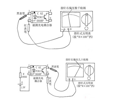
It should be noted that: the forward conduction voltage of common infrared light-emitting diodes in optocouplers is lower than that of ordinary light-emitting diodes, which is generally below 1.3V, so it can be directly measured with the "R × 100" resistance block of pointer multimeter, and the battery g voltage in Figure 1 (b) can be taken as 1.5V (with a 5-cell). The connection of the multimeter shown in Fig. 1 (a) can be used to directly replace the forward voltage (i.e. resistor R and battery g) at the input terminal shown in Fig. 1 (b), so as to make the measurement more convenient, but a multimeter is needed.
As for the detection of multi-channel optocoupler, the pins of all light-emitting diodes should be identified first, and then the pins of corresponding photosensitive triodes should be determined. For the optocoupler in the line, the best detection method is "comparison method", that is, remove the suspected optocoupler, use a multimeter to measure the forward and reverse resistance values of its internal diode and triode, and compare with the corresponding pin measurement value of the same type of good optocoupler. If the resistance difference is large, the photoelectric coupler under test has been damaged.
2. Discriminator detection method.
Many years ago, according to the principle of optocoupler, the author designed and made a small discriminator which can quickly judge the quality of optocoupler. The circuit is shown in Fig. 2. When the input and output pins of the optocoupler are correctly inserted into the four corresponding sockets of the discriminator, if the LED VD1 and VD2 flash synchronously, the optocoupler is in good condition. If VD1 does not flash, it means that the light emitting tube inside the optocoupler has been open circuit; if VD1 flickers, but VD2 does not light or emits constant light, it indicates that either the light-emitting tube in the optocoupler fails or the photosensitive transistor has been opened or broken down.